
If the machine seems to be firing with very low power, or not firing at all, there could be a problem with the Power Supply Unit or the Laser Tube. These instructions will help you get m/A readings from the machine’s Power Supply Unit by using the provided Green Resistor with Black and Red Wire Leads in lieu of the Laser Tube. This test will help identify and possibly solve problems between the Laser Tube and the Power Supply Unit.
Before you start
Disclaimer: Even though every attempt is made to ensure this information is complete and accurate, it is impossible to account for all possible circumstances or situations. Please consult with a qualified Boss Laser Technician before attempting to perform any work you are not qualified to do. Lasers can be hazardous to work on; be sure to take all necessary safety precautions. Failure to do so may result in property damage or personal injury. Be sure that the work that is performed does not disable any safety features on the laser system.
Before You Start
Tools you will need
Gather these before opening the machine so the test runs start to finish without a parts hunt.

- Silicone Sleeve – May be connected to the Laser Tube
- Small 6-Pin Bypass Plug with Red Wire Loop – In your machine toolbox
- Green Resistor with Black and Red Wire Leads – In your machine toolbox
- Telescoping Mirror (Optional)
Step 01
Prepare the resistor and open up meter access

Steps
- Use the Silicone Sleeve shown in the image to cover the Green Resistor with Black and Red Wire Leads completely, especially over the Red (High Voltage) Wire lead. This is important as we want to avoid any type of arcing while test fires are taking place.
- Open the upper right-hand door of the machine and locate the bottom of the Milliamp meter. This will give you the space needed to run the wires from the Green Resistor that will be connected to the High Voltage Connector from the Power Supply Unit at a later step.

Step 02
Connect the resistor to the milliamp meter
We will connect the Green Resistor found in the toolbox to the Power Supply Unit and the m/A meter on the machine and then connect the 6-Pin Bypass Plug to the Power Supply Unit for some test fires. To do this, please follow these steps:
Steps
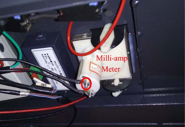
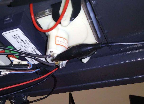
- Connect the Alligator clip from the Black lead on the Green Resistor to the circled Lug displayed on the image. Please make sure to remove any glue that is on the lug prior to connecting the Alligator clip.
- Attach the Alligator clip as shown in the image. Please make sure that the Alligator clip makes good contact with the lug and that there’s enough slack on the wire lead as to not pull down on the Alligator clip and cause it to disconnect.
Step 03
Disconnect the High Voltage Connector and connect the red lead
Steps
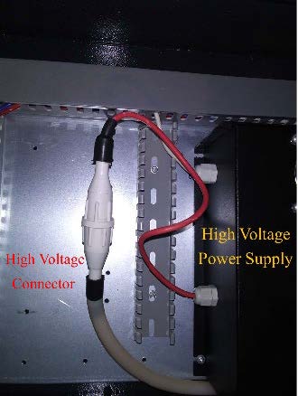
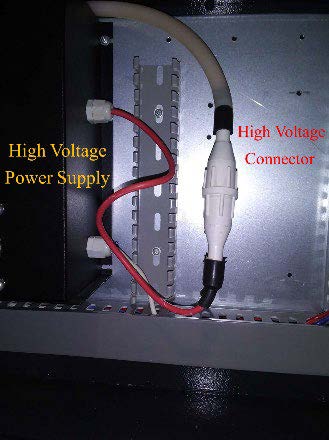
- Open the big white door on the right-hand side of the machine and locate the High Voltage Connector from the Power Supply Unit.
- On some machines it looks like this:
- On some machines it looks like this:
- Unscrew / Disconnect the High Voltage Connector. Please be careful when disconnecting the High Voltage Connector as we don’t want to break the post on the inside of the Connector. Once unscrewed all the way, the Connector should pull apart / separate easily.
- Connect the Red Lead from the Green Resistor as shown on the image. Please make sure that the Alligator clip has a good grab on the post inside of the Connector.

Step 04
Install the 6-Pin Bypass Plug

Steps
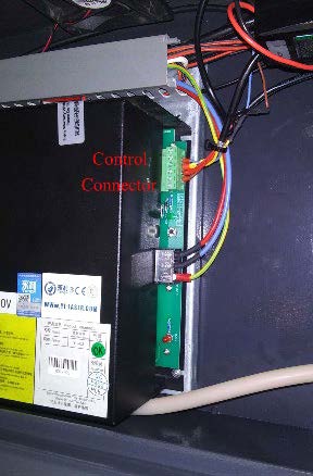
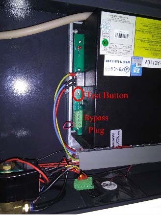
- Locate the 6-Pin High Voltage Power Supply Control Connector on the Power Supply Unit.
- On some machines it looks like this:
- On some machines it looks like this:
- Unplug the 6-Pin High Voltage Power Supply Unit Control Connector by pulling on it and then install the 6-Pin Bypass Plug in its place. Installing the 6-Pin Bypass plug will allow you to send test pulses directly from the Power Supply Unit. This helps identify where the problem is coming from as it will bypass the machine Control Panel and isolate the Power Supply Unit.
- On some machines it looks like this:
- On some machines it looks like this:

Step 05
Run the resistor test and read the Power Supply Unit
Steps
- Turn the machine back on and let it go home.
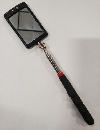
- Have someone watch the Milliamp meter while you press the test button on the Power Supply Unit. If you don’t have anyone to assist you, use a telescoping mirror like the one shown here in the image to help you see the m/A gauge as you press the test button.
- The Milliamp meter is located at the top right-hand side of the machine as shown in the image.
- Good Power Supply Unit test readings are as follows:
70W Power Supply Unit: 26 – 29 m/A
105W Power Supply Unit: 33 – 43 m/A
155W Power Supply Unit: 47 – 50 m/A
If you get a good reading in range
If the test fire generates a good reading within the range for your Power Supply Unit, suggesting that the Power Supply Unit is outputting power correctly, please turn the machine off and follow these steps.
If the reading is below range
If the test fire generates m/A readings that are below these numbers for your Power Supply Unit, that would be a good indication that there’s a problem with the power output of the Power Supply Unit.

Step 06
Reconnect the Laser Tube and re-test
Steps
- Disconnect both the Black Wire test lead from the Green Resistor that is clipped to the bottom of the Milliamp meter and the Red Wire test lead that is clipped to the High Voltage Wire coming from the Power Supply Unit.
- Reconnect the High Voltage Connector.
a. This will bring the Laser Tube back into play. - Reinstall the High Voltage Silicone Sleeve on your Laser Tube if that is the one you used for the previous steps.
- Once that has been completed, press the test button on the Power Supply Unit again to get test readings with the Laser Tube in play.
- Good test readings with the Laser Tube back in play are as follows:
70W Laser Tube: 21 – 25 m/A
80W Laser Tube: 21 – 25 m/A
105W Laser Tube: 23 – 25 m/A
155W Laser Tube: 28 – 31 m/A
If the reading is in range
Readings within the ranges listed above indicate the Laser Tube and Power Supply Unit are both working correctly.
If the reading is below range
If the test fire generates readings below these numbers with the Laser Tube back in play, that would be a good indication that there’s a problem with the Laser Tube.
Document Number: Simplified Resistor Test WI 855-718 Revision Number: 001 Revision Date: 4/4/2025
After Testing
Have your results ready for Tech Support
Please contact Boss Laser Tech Support at 407-878-0880, or via email at techsupport@bosslaser.com with any additional questions.
Related guide: Laser Not Firing: Interlock Testing · Back to the Support Hub