
In the event that your laser does not fire, work through these interlock tests in order — the results tell Technical Support exactly which interlock is keeping the laser from firing. If you need help at any point, send us a support request.
Watch First
Watch the video walkthrough
Before You Start
Tools you will need
Gather these from the machine tool box before opening the machine. The door-sensor test also uses a magnet, and the gold-PSU test uses the small screwdriver from the tool box.
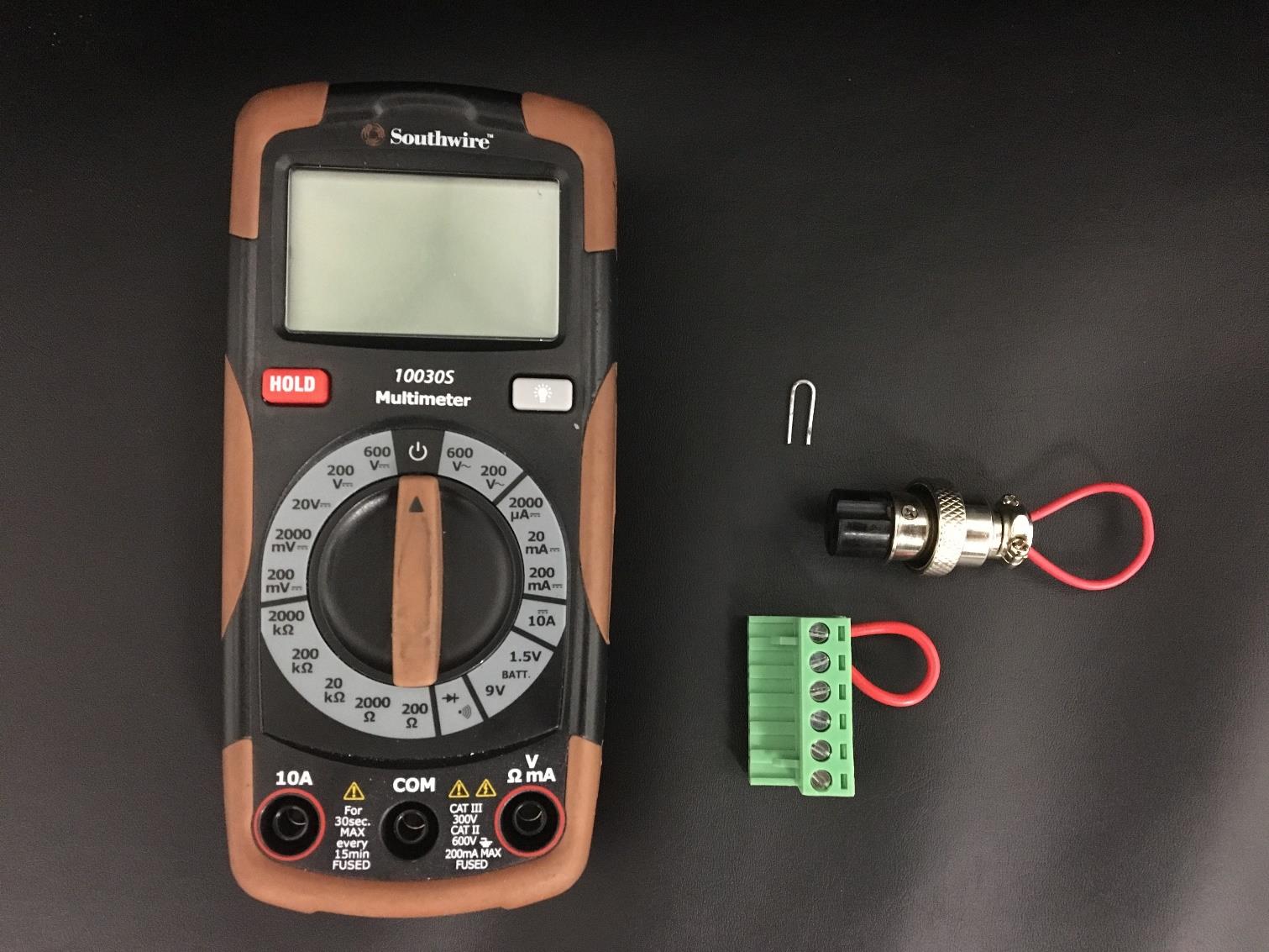
- Chiller bypass
- 6-pin bypass
- Interlock bypass OR paperclip
- A multimeter
Safety first
Laser power supplies contain high-voltage components. Turn the machine off before disconnecting or reconnecting plugs. Bypasses are for temporary diagnostic testing only and should be removed before normal operation.
Two-Minute Rule-Out
Check the simple causes first
A head that runs the job with no burn usually means the beam is blocked by a protection mode. Before opening any panel, confirm each of these:
- Water chiller is on and water is actually flowing — no flow means no fire
- All doors and the lid are fully closed — open interlocks cut the beam
- Minimum power on the control panel is at least 5% — below that the tube will not fire at all
- Key on, E-stop released, breaker not tripped, fuse intact, plugged into live power
Rule-out list from the Boss owner’s-manual troubleshooting table (“Machine Turning On But Not Firing”). If everything above checks out, continue with the interlock tests below.
Step 01
Make sure the power supply is powering on
Goal: prove the laser power supply itself has power before testing any interlock.
Steps
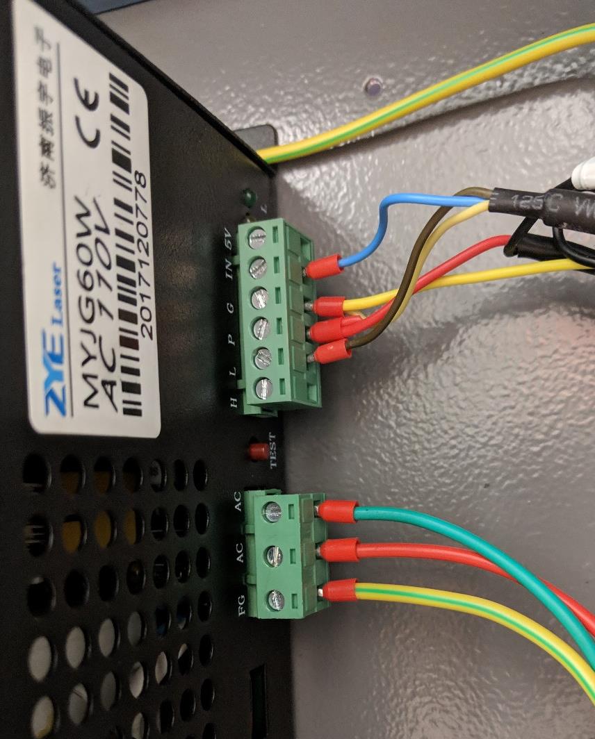
- Locate your power supply unit, this is found through the right side of the machine through the large white door on the bottom.
- The power supply is either going to be gold or black in color. It will have a six-pin green connector and a three-pin green connector going into it. On the other side it will have a larger red wire and black wire as well.
- Take a look at the power supply with the machine powered on, do the lights work and are the fans on the power supply spinning?
a. If yes, please move onto the testing below.
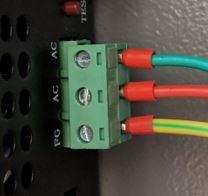
b. If no, please check the three-pin connector along the side of the machine on the yellow wire with a green tracer and the red wire. This would be your hot lead and ground lead.
Lights and fans on
The power supply is powering on. Continue to the six-pin bypass test.
120V in, but no power-up
The power supply is faulty and will need to be replaced.
⚠ Send a support request for a replacement power supply.
Step 02
Six-pin bypass test for 60W, 100W and 150W machines
Goal: bypass the interlock circuit at the power supply to prove whether an interlock is the problem.
Steps
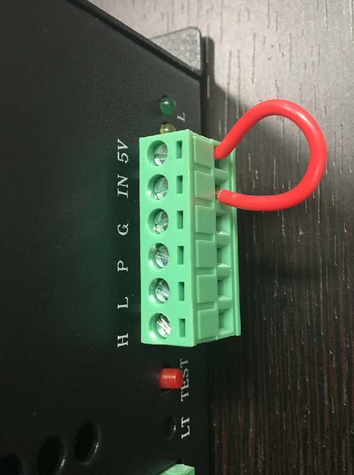
- Locate your 6-pin bypass.
- Make sure that your machine is powered off.
- Locate your mA meter, this will be above your laser keypad and temperature gauge.
- Locate your power supply (PSU). Normally will be on the right-hand side of your machine.
- Take out your 6-pin from the laser power supply.
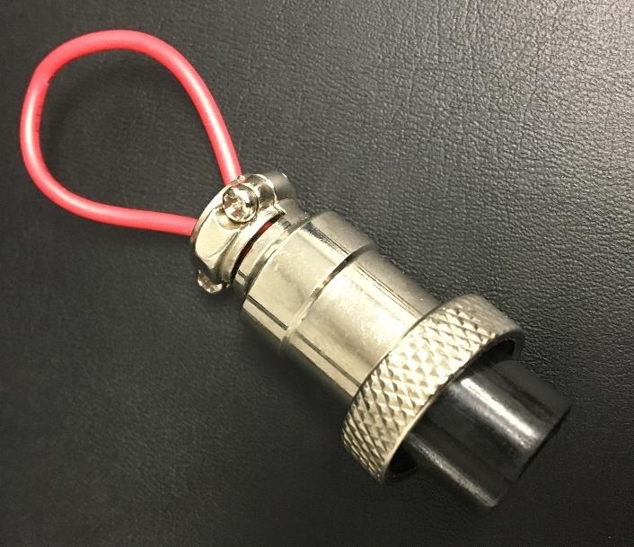
- Replace this connector with the six-pin found in your tool box with the wire loop.
- Locate your test button on the power supply, it should be a red push button that says test or laser.
- Power your machine back on.
- Use the test button while viewing the mA meter.
Laser fires
You have an interlock issue. Continue testing below to find which interlock it is.
Laser does not fire
Complete the Simplified Resistor Test instead — the issue may not be an interlock.
Step 03
Six-pin bypass test for a gold PSU
Goal: the same bypass test, adapted for gold power supplies — these pulse from the keypad instead of a test button.

Steps
- Locate your 6-pin bypass.
- Using the screwdriver provided in your tool box you will remove the looped wire from the six-pin connector that was found from the tool box.
- Make sure that your machine is powered off.
- Locate your mA meter, this will be above your laser keypad and temperature gauge.
- Locate your power supply (PSU). Normally will be on the right-hand side of your machine.
- Take out your 6-pin from the laser power supply and add the wire that you removed to pins 3 & 4 of your 6-pin connector. This will go on top of what is already there in addition.
- Plug the 6-pin connector back into the laser power supply.
- Power your machine back on.
- Go to the keypad of your laser machine, and make sure the power is set to 95%.
- Once power has been verified, hit the pulse button on the key pad.
Laser fires or mA meter moves
You have an interlock issue and you may continue testing below.
Laser does not fire
Complete the Simplified Resistor Test procedure.
Step 04
Testing the door sensor
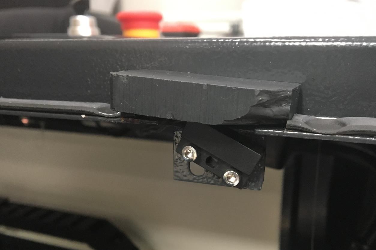
We will be testing the door sensor. This is a safety switch that tells your laser not to fire with the door open. You will need a magnet to do the following test. Your regular 6-pin connector should be plugged in, not your 6-pin bypass.
Steps
- What you are going to do is place the magnet directly on top of the door contact. The door contact will be in the door jamb when you lift the hood of the machine up.
- With the magnet on top of the door contact you will go to the keypad and see if the laser will fire.
- If the laser fires, then the door interlock is the issue, and this will need to be adjusted. Since the laser fires with the magnet on the contact this indicates that it does not make good contact with the hood magnet.
- To fix this you are going to loosen the two Allen screws on the contact and raise the contact up as high as it can go (still at an angle) and then drop the hood down and see if the laser fires with the door closed.
Fires with the magnet
The door interlock is the issue. Adjust the contact as described, then re-test with the door closed.
Does not fire with the magnet
Continue testing at the chiller signal cable port located on the back of the machine.
Step 05
Testing the water chiller signal cable
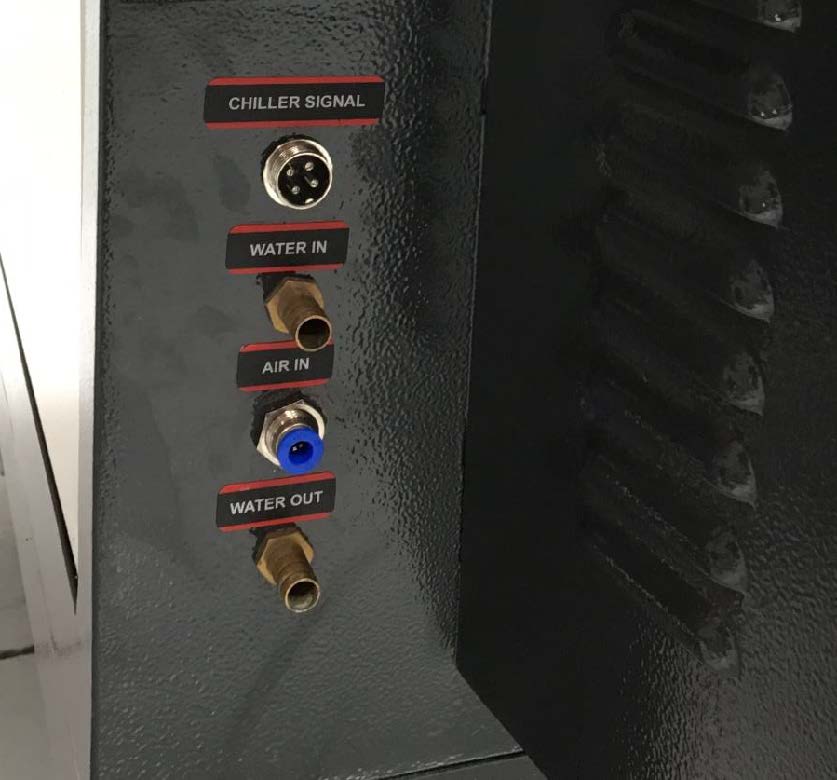
We will be testing the chiller signal cable port, this will be located at the very back of the machine, labeled as chiller signal.
Steps
- Locate the chiller signal cable, this will be found on the exterior of the machine labeled chiller signal.
- If the cable from the chiller to the machine is in its place you will remove this wire from the connector.
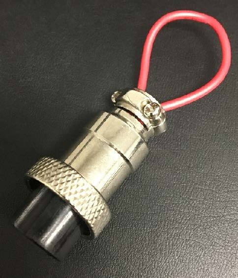
- With this connector removed you will go to your tool box and locate the chiller bypass plug.
- Go to the back of the machine and install the chiller bypass plug.
- With the bypass plug installed you will go to the keypad of the machine and see if the laser will fire.
Laser fires
The cable going to the chiller has gone out and you will likely need a new one.
Laser does not fire
Move on to the final interlock test — the water flow sensor.
Leave the magnet on the door and the chiller bypass in the signal cable port while you continue.
Step 06
Testing the water flow sensor
Goal: bypass the flow sensor to see whether it is blocking the beam — and whether it just slid out of position.
Steps
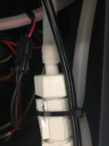
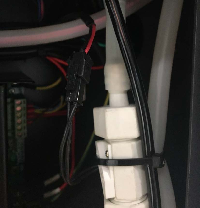
- Locate the water flow sensor, this can be found in-between the power supply and the frame of the machine, it will be a large white cylinder that will have the water in and out hoses attached.
- Once this has been located you will remove the male and female connector to disconnect the wiring of the water flow sensor.
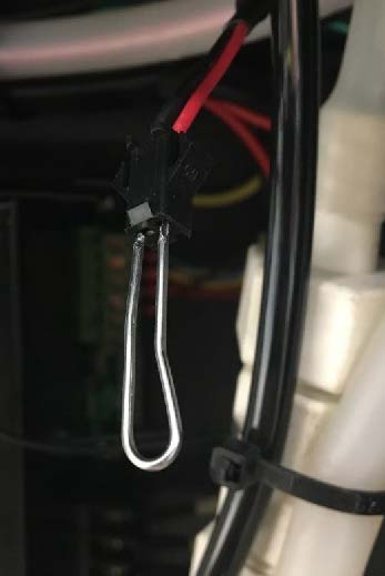
- With the wiring disconnected you will take your paper clip and plug it into the female end of the connector, one end of the paper clip on one side and the other end on the other side.
- With the water flow sensor completely bypassed you will see if the laser machine will fire from the keypad.
- If the laser fires, then the water flow sensor is the culprit and will need to be replaced.
a. Before we replace the water flow sensor we need to verify if it just slid out of position
b. Please take the paper clip off and reconnect the male connector to the female connector as it was before
c. Take a small screwdriver and loosen the screws on the plate that has the wires going to the connector
d. Slide the plate to the middle or opposite end(s) of the screw groove and retighten the screws (you may need to repeat steps d – f up to 2 times)
e. Turn the machine back on
f. Press the Pulse or Laser button on your Control Panel
g. If the laser fires, then you have fixed your issue and there’s no need to continue troubleshooting or replace the Water Flow Sensor as it was just out of position
h. If the laser still doesn’t fire after moving the plate to all of the other possible positions on the groove, then the Water Flow Sensor must be replaced
Laser fires bypassed
The water flow sensor is the culprit — re-seat it per the sub-steps, and replace it only if repositioning doesn’t fix it.
Laser does not fire
You will need to check for continuity using a multimeter — continue below.

Step 07
Checking for continuity
If none of the interlock testing checks out, you will need to run continuity tests on all components until you find the culprit.
Steps
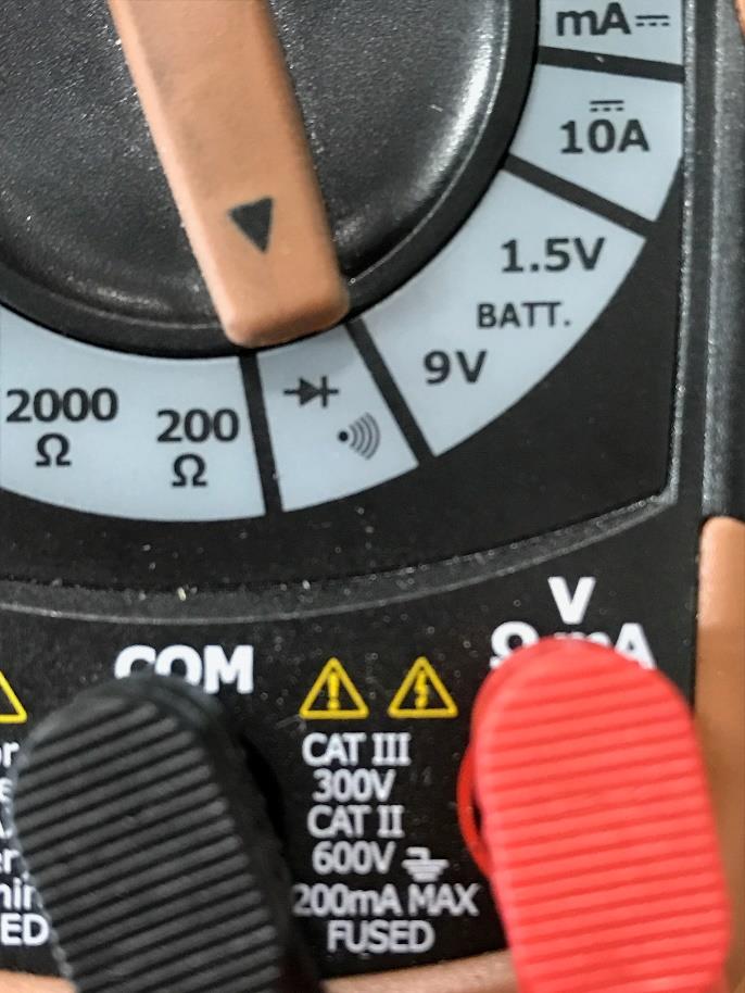
- Turn your multimeter to check for continuity with an audible beep, to do this you can refer to the picture, this shows where the meters setting should be set for.
- When you tap the red and black leads together while in this setting it will beep, confirming that the circuit is complete and has continuity on it.

Step 08
Door sensor male end continuity
Goal: prove electrically whether the door contact closes when the magnet is present.
Steps
- Turn the machine off.
- Place a magnet on the door contact.
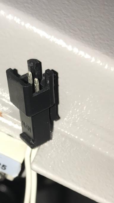
- Unplug the door contact by tracing down the wire to the female/male connector.
- Turn your meter on and set it for continuity.
- Once you have this plug undone and the male end in your hands, you are going to put the meter leads on both silver prongs, one prong for red and one for black.
- With a magnet on the door contact you should have continuity, and once the magnet is gone, continuity will disappear along with the beeping.
Yes continuity
Your door contact is good — you are losing continuity somewhere else. Proceed with checking the water flow sensor.
No continuity
The door contact is bad — send a support request.
Step 09
Testing the water chiller signal
The last interlock switch, which is the water chiller signal cable. It’s located on the back of your machine, where your chiller plugs in. If you have a water pump you will already have this plugged in.
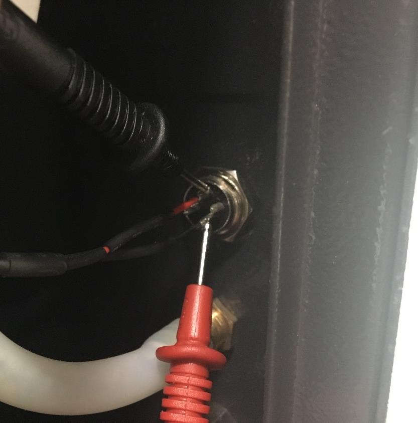
Steps
- Making sure all the other interlocks we have tested are plugged back in.
- Locate your chiller bypass.
- Plug the chiller bypass into the chiller signal port on the back of the machine.
- Have machine off and the water/chiller on.
- Put the multimeter on the inside of the chiller signal port where the wires attach, red on one black on the other, do you have continuity?
Yes continuity
The bypass plug is good and the laser should be able to fire. Continue to the final check below.
No continuity
The issue is coming from either the bypass plug or the port itself — send a support request.
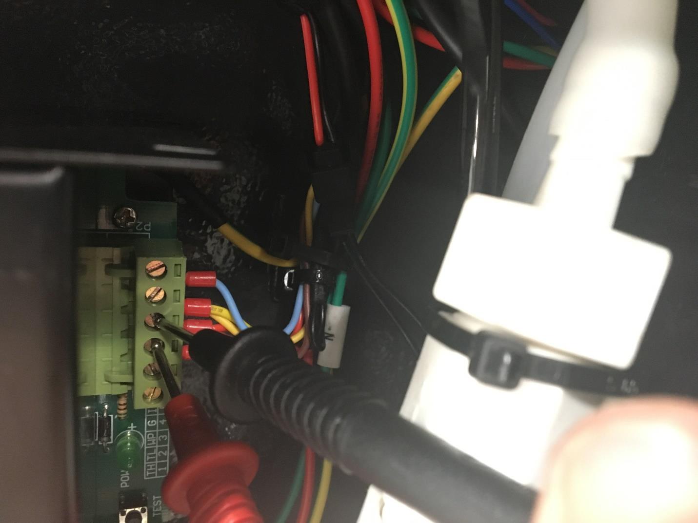
Final check: if all the interlocks have continuity and check out, check the six-pin connector on the power supply by putting the leads on pin 3 and pin 4. Continuity and a beep there means you are ready to fire your laser. If you still do not have continuity at this point, please contact Technical Support.
After Testing
Restore the machine, then have your results ready
Reconnect all plugs and remove any temporary bypass pins or connectors before normal operation. When you contact Technical Support, tell us which test passed or failed, whether the laser fired from the power-supply test button, and whether pins 3 and 4 had continuity.
Related guide: Simplified Resistor Test for Boss CO2 Lasers · Back to the Support Hub