
FC Series
Sheet → finished part
Operator
Per-material settings
Prepare and load the sheet → nest and program the parts → set focus and assist gas for that material and thickness → pierce a starting hole → run a short lead-in into the profile → cut the contour → unload and inspect. The machine automates most of it. The two steps that decide whether your parts are sellable are the pierce (the most punishing moment for your nozzle and optics) and the lead-in (what keeps the pierce blemish off the finished edge). Most bad edges trace back to gas, focus, or speed — checked in that order.
1 · Material prep and loading.
Flat, clean, and identified. Each of those earns its place:
- Flat — the machine sets focus relative to a plane. A warped or bowed sheet moves the material out of focus mid-cut, which shows up as a cut that works at one end of the bed and not the other.
- Clean — oil, heavy scale, and residue change how the surface takes the beam and can flare at the pierce.
- Identified — “some kind of stainless” is not a material spec. Alloy and thickness drive gas choice and settings, and coated stock (galvanized especially) brings fume considerations that bare steel doesn’t.
Know what you’re loading
Unidentified coated or plated stock is a genuine hazard, not a nuisance. Galvanized releases zinc fume; anything with a chlorinated coating or plastic film can produce corrosive or toxic products. If you can’t confirm what the material and its coating are, don’t cut it — and make sure extraction is running regardless.
2 · Programming and nesting.
Your CAD profile becomes toolpaths. The decisions made here set both your material yield and your cycle time:
| Decision | What it does |
|---|---|
| Nesting | How parts are packed on the sheet — directly sets how much you scrap |
| Lead-in placement | Puts pierce damage in scrap rather than on a visible edge |
| Cut order | Interior features before the outer profile — cut the outside first and the part can shift or drop |
| Microjoints / tabs | Tiny uncut bridges holding parts in the sheet so they don’t tip into the bed or get blown out of position |
| Common-line cutting | Adjacent parts sharing one cut — saves time and material where tolerance allows |
None of this was in the source article, and all of it is what separates a program that runs from a program that produces good parts economically.
3 · Focus and gas — set before you cut, not during.
Focus position sets where the beam waist sits relative to the sheet, and it changes with thickness — thin material generally wants focus at or near the surface, thicker material wants it driven into the sheet so the beam stays effective through the depth. Modern machines set this automatically from the material and thickness you select, which is exactly why telling the machine the truth about your stock matters.
Gas is chosen at the same time, and it’s a real decision rather than a default:
| Gas | Use it for | Edge |
|---|---|---|
| Oxygen (O₂) | Mild/carbon steel, especially thicker | Faster — the oxidation reaction adds energy — but leaves an oxidized edge that usually needs cleaning before paint or weld |
| Nitrogen (N₂) | Stainless, aluminum, anything needing a finished edge | Bright, clean, weld-ready — slower and consumes considerably more gas |
| Compressed air | Thinner material where cost matters | Between the two; quality depends heavily on air dryness and filtration |
Pressure matters as much as the choice — the full oxygen-vs-nitrogen decision →
4 · The pierce — the step everyone underestimates.
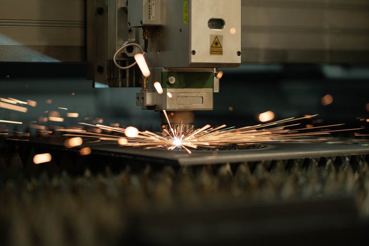
Before any contour can be cut, the beam has to get through the full thickness from a standing start. That’s fundamentally harder than cutting, where the beam is already through and simply advancing.
What makes it the risky moment:
- It takes far longer than cutting the same distance — energy is going into one spot until it breaks through. On a nest with many holes, total pierce time can rival total cut time.
- It ejects molten material upward, toward the nozzle and the protective window — which is why those are the consumables that suffer.
- It’s a heat concentration, so it leaves a larger affected area than the cut does. Hence lead-ins.
Thicker material commonly uses a staged or ramped pierce — stepping power and gas rather than going to full power immediately — to break through in a controlled way rather than blasting a crater.
Where pierce settings come from
Pierce parameters are genuinely process- and machine-specific, and they are not a single number you can look up. Published cutting charts are starting points for cutting; pierce guidance for your particular machine, thickness, and gas is something to get from Boss rather than infer from a chart.
5 · Cutting the contour.
Once through, the head follows the programmed path while the assist gas clears molten material out of the kerf below. Steady state, and the least eventful part of the process when the setup was right.
Two things still vary here: corners and small features, where the head slows and heat concentrates (which is why tight internal radii can look different from long straight runs), and the last part of a nest, where an increasingly cut-up sheet is less stable and more prone to shifting.
6 · Unload, inspect, and read the edge.
The edge tells you what your settings did. Learning to read it is the fastest diagnostic skill in the shop:
| What you see | Most likely cause | Check first |
|---|---|---|
| Dross clinging underneath | Melt isn’t being cleared from the kerf | Gas pressure, then nozzle condition/size, then focus, then speed |
| Rough, striated edge | Speed and power mismatched to thickness | Slow down before adding power |
| Tapered edge (wider at top) | Focus position wrong for the thickness | Focus setting; confirm sheet is flat |
| Discoloured/oxidized edge on stainless | Cutting with O₂ or air where N₂ was needed | Gas selection |
| Burn marks at corners/small holes | Heat concentrating where the head slows | Corner strategy and lead-in placement |
| Was fine, now isn’t | Contaminated protective window or worn nozzle | Inspect optics and nozzle before touching any setting |
Then there’s the ordinary finishing work — deburring, removing microjoint witness marks, and cleaning oxidized edges if they’re going to be welded or painted.
Cutting something shiny?
Copper, brass, and highly polished aluminum change this process meaningfully — particularly the pierce, which is where back-reflection risk concentrates. That gets its own treatment. How to cut reflective metal →
7 · FAQs
Frequently asked
The Fiber Cutting Process, Step by StepQWhat are the steps in fiber laser cutting?
Prepare and load the sheet, nest and program, set focus and assist gas for the material and thickness, pierce, run a lead-in into the contour, cut the profile, then unload and inspect. The pierce and lead-in are the two most often skipped in descriptions and most often responsible for scrap.
QWhat is piercing?
Punching the initial hole through the sheet before the contour can start. The beam has to get through full thickness from a standstill, which takes longer and concentrates far more energy than cutting — so it throws melt upward and is the likeliest moment to damage a nozzle or protective window.
QWhat is a lead-in?
A short entry path from the pierce point into the part contour, placed in scrap so pierce damage never lands on the finished edge.
QWhy is there dross on the underside?
Molten material isn’t clearing the kerf. Usually gas pressure too low, wrong gas for the material, a worn or wrong-size nozzle, focus off, or speed mismatched to thickness. Check gas and nozzle first.
QWhat are microjoints?
Tiny uncut bridges left deliberately so finished parts stay attached to the sheet instead of tipping into the bed or shifting. They’re snapped or cut free afterward and leave a small witness mark to dress.
8 · Related in this series.
Part of Fiber & Metal Cutting:
- Which metals cut well — and how thick
- How to cut reflective metal — where this process changes
- Melt-and-blow cutting — the physics at the kerf
- The parameters you actually set — which dial to turn first
Keep exploring
One idea leads to the next.
Metal cutting rewards getting the details right. Follow the rest of the series, or talk it through with someone who runs these systems.